![[Translate to English:] Glasfaser Installationsprozess](/fileadmin/_processed_/8/c/csm_Glasfaser-installationsprozess_1_2e3cf644ab.jpg "[Translate to English:] Glasfaser Installationsprozess")
Feb
2026
Installing and Measuring Fiber Optics. Practical Guide for Installation, Testing, and Acceptance
Understanding Fiber Optics. Fundamentals of Fiber Cabling
A clean fiber optic installation does not require deep knowledge of physics. What matters is a basic understanding of how fiber optics work and what influences quality. Those who understand these relationships can avoid many problems before they arise.
The principle is simple. Light is guided through a glass core and contained within it by differences in refractive index. As long as this optical path remains clean and undisturbed, transmission is reliable. Any disturbance directly affects the signal.
The key quality metric is attenuation. It describes signal loss between transmitter and receiver. Attenuation is not only caused by fiber length, but primarily by transitions. These include connectors as well as fusion and mechanical splices. Fiber optics tolerate neither bends nor contamination on end faces.
A simplified analogy. Think of fiber as a water-filled hose. Any obstruction disrupts the flow and reduces pressure. In fiber optics, this pressure loss corresponds to attenuation.
An installation is considered good when total attenuation remains within the specified budget.
Fiber type also plays a role. Multimode is typically used over short distances, for example within buildings. Singlemode is suitable for longer distances and is increasingly used even where multimode was previously standard. Mixing the two systems is rarely useful and leads to additional costs. Plan your fiber type carefully, or verify what is already installed.
Connectors and polish types are equally important. The distinction between UPC and APC is particularly critical. They are mechanically compatible but not optically. Mixing polish types leads to high attenuation and reflections, even if the connection appears correct. Identification is simple. APC connectors and adapters are always green.
Cleaning is often underestimated. Clean end faces are not optional but essential. Contamination is one of the most common causes of increased attenuation and unstable measurements. Cleaning itself is straightforward. A simple click cleaner can already resolve many issues.
In summary. Fiber optics are not a delicate specialty medium. Like copper cabling, they have specific handling requirements. Clean transitions and a clear understanding of attenuation are the foundation for a stable and measurable installation.
The Installation Process in Practice
Before diving into individual steps, it is helpful to look at the overall process of a fiber optic installation. From exposing the fiber, cleaning, cleaving, and splicing, through to measurement and optional OTDR analysis, each step follows a defined sequence.
This sequence is not a theoretical construct but everyday practice on-site and in technical rooms. Each step builds on the one before it. If a step is skipped or carried out inaccurately, the effects will usually become apparent later during measurement.
The following overview presents this process in a compact, step-by-step format. It makes clear that fiber optic installation is less about isolated manual tasks and more about a structured workflow in which preparation, inspection, and documentation belong together.
With this overall picture in mind, we will now look at the individual phases in more detail, starting with preparation and installation.
![[Translate to English:] Infografik Glasfaser-Installationsprozess](/fileadmin/images/blog/Infografik-Glasfaser_3.jpg "[Translate to English:] Infografik Glasfaser-Installationsprozess")
Preparation and Installation. Cleanliness Beats Speed
A clean installation starts with the working environment, not the fiber. Adequate lighting, an organized workspace, and a calm setting are prerequisites for precision.
When exposing and preparing fibers, structure is key. Cables must be opened in a controlled manner, fiber slack properly managed, and consistent lengths maintained. Inaccurate cuts or unnecessary tension may not have immediate effects but can later lead to increased attenuation or mechanical issues.
Cleaning is an integral part of preparation. After stripping the coating, fibers and connectors must be consistently cleaned. Contamination is one of the most common causes of problems during splicing and measurement.
During cleaving and splicing, preparation quality determines the outcome. A clean, perpendicular cut is essential for a good splice. Reworking poorly prepared fibers wastes time and rarely improves results. Repeating a step correctly is usually more efficient than trying to fix a suboptimal result.
After splicing, splice protection and proper storage follow. This is not only about mechanical protection but also organization. Maintaining bend radii and neat placement in splice trays or panels are quality indicators and simplify future work.
Typical errors arise mainly from time pressure. Cleaning steps are skipped, cuts are reworked, or storage is improvised. This may seem faster in the short term but leads to rework and troubleshooting later. Cleanliness beats speed. Structured execution of each step ensures stable and reproducible results.
![[Translate to English:] Tier1-Zertifizierer SpicyONE](/fileadmin/images/blog/Tier1-Zertifizierer-SpicyONE_2.jpg "[Translate to English:] Tier1-Zertifizierer SpicyONE")
Testing and Measuring Fiber Optics. Tier 1 Measurement and OTDR
Testing and measurement mark the transition from manual work to objective evaluation. The correct sequence is critical.
Start with a visual inspection using a visible light source. This helps identify major issues such as breaks, defective connectors, or tight bends. Escaping light immediately reveals problem areas. This does not replace measurement but saves time by eliminating obvious faults early.
![[Translate to English:] Laserlichtquelle](/fileadmin/images/blog/Laserlichtquelle_4.jpg "[Translate to English:] Laserlichtquelle")
Next is connector inspection. Cleaning alone does not guarantee cleanliness. Contamination or scratches on the end face are not visible to the naked eye but can significantly increase attenuation. Video microscopes enable proper inspection. The process is clear. Clean, inspect, then measure. This step reduces measurement errors and disputes during acceptance.
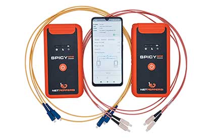
Actual evaluation is performed using Tier 1 measurement. It measures total attenuation from end to end, including fiber, splices, and connectors. What matters is not the absolute value but comparison with the planned attenuation budget. Modern Tier 1 testers support this with clear pass/fail results and proper documentation.
Thresholds are clear. If attenuation exceeds limits, troubleshooting is required. If it remains below the target value, the installation is acceptable.
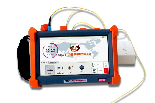
OTDR is used for detailed analysis or fault localization. It complements but does not replace Tier 1 measurement and is not mandatory for acceptance. Understanding the difference allows targeted use of both methods.
Structured testing results in fewer issues and reliable, traceable outcomes.
Read also our blog article:
Tier-1 Measurement or OTDR. Choosing the Right Method for Fiber-Optic Acceptance

When Things Don’t Match. Typical Issues from Practice
In practice, installations often appear clean, splices look correct, yet measurements fail. Sometimes a single issue causes the failure, sometimes it is the combination of several small errors.
A common scenario is increased attenuation despite a clean splice. Causes are often subtle. Slightly contaminated connectors, poor fiber routing in trays, or tight bend radii. Individually minor, collectively critical.
Measurement tools help identify such issues. A visible light source or an OTDR can evaluate each component along the link. A faulty connector at the far end or a bend at a specific distance can be quickly located.
Another frequent issue lies in the measurement equipment itself. Fluctuating results or consistent threshold violations may indicate measurement errors. Keep equipment clean and regularly verify proper operation. A reference link with known values is useful.
Important. A measurement is always a snapshot under defined conditions. Adding components later, such as active equipment (switches, routers) or passive components (splitters, patch cords), affects overall system performance.
Practical expertise means interpreting measurements correctly. Most issues can be explained and resolved when considering the entire process, not just the final result.
Checklist for Installation, Testing, and Measurement
Preparation and Installation
- Working environment prepared, sufficient lighting and organization
- Cable opened correctly, fiber slack properly planned
- Fibers properly prepared and consistently cleaned
- Splices strain-relieved and neatly stored
Connectors and Transitions
- Connectors cleaned before each connection
- End faces inspected, no visible damage
- Correct polish types used, no UPC/APC mixing
Testing and Measurement
- Visual inspection performed
- Reference properly set
- Measurement completed and compared to attenuation budget
- Results documented
Conclusion
A successful fiber optic installation is not the result of isolated perfect actions but of a consistent, end-to-end process. Preparation, installation, testing, and measurement are interconnected. If one step is neglected, it usually becomes apparent later.
Structured work reduces error sources and saves time. Using measurements as a diagnostic tool rather than just a pass/fail criterion increases confidence. Fiber optics do not require special talent but consistent execution. This is the key to stable, reproducible results.
Anyone who wants to confidently implement planning, installation, and testing will find concise, practical expertise on fiber optic installation in our product catalog: Successfully Installing and Testing Fiber Optic Networks

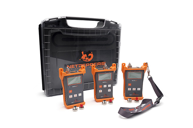

OPM200
One device - 4 functions: Power Meter, Visual Fault Locator, Cable Tester and Torch